3D frames and trusses
Nodes, members, releases and supports in tables, with the structure beside them. Steel shapes, concrete rectangles or your own section properties.

Model a frame in three dimensions, analyse it under static and seismic loads, and design its steel and concrete members, slabs and footings by NSCP 2015. One desktop app, with every number's calculation a click away.
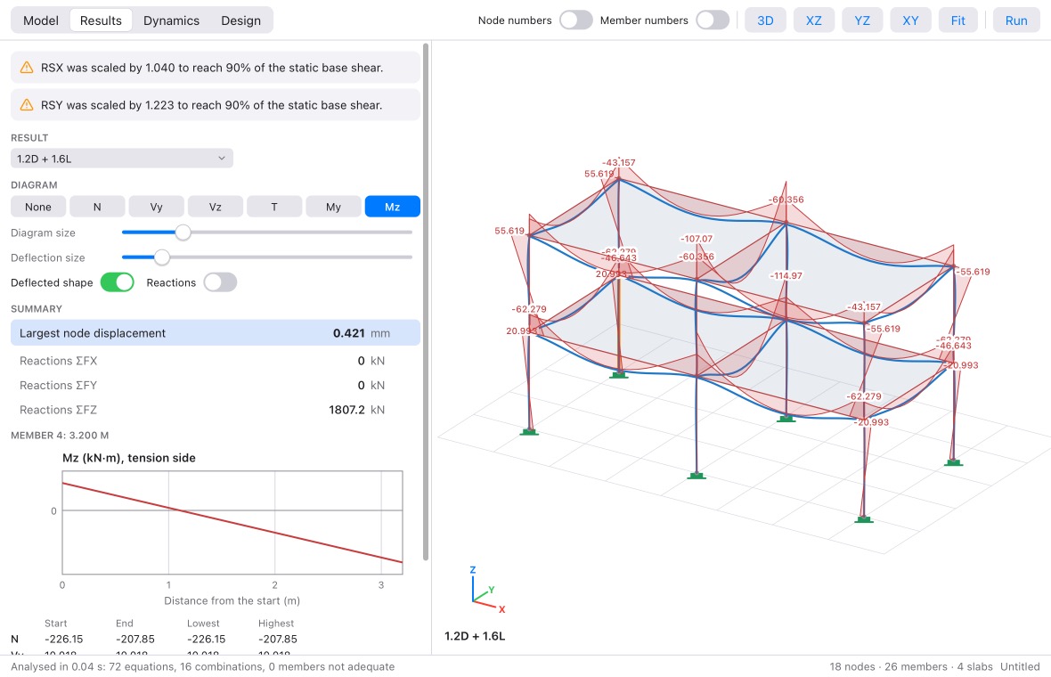
From the model to the bar schedule, in four tabs: Model, Results, Dynamics, Design.
Nodes, members, releases and supports in tables, with the structure beside them. Steel shapes, concrete rectangles or your own section properties.
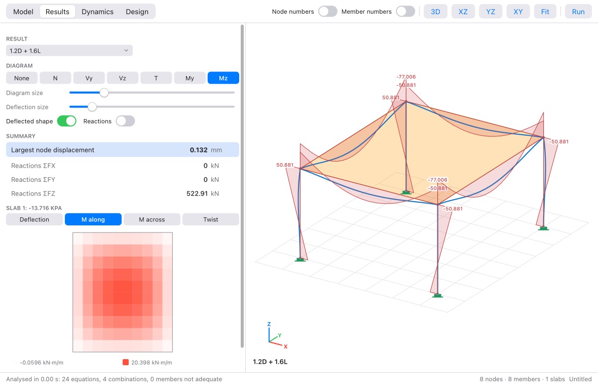
Every load case and combination: deflected shapes, reactions, and diagrams of N, Vy, Vz, T, My and Mz. Combinations can be taken to second order.
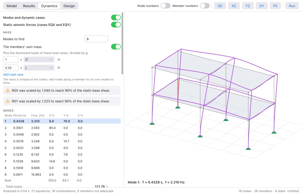
Natural modes you can set swinging, the response spectrum method with CQC or SRSS, and the response over time to a ground motion record.
The NSCP 2015 design spectrum from Ca and Cv, the static force procedure of Section 208.5.2, and the spectrum scaled to its base shear.
NSCP 2015 Chapter 5 (AISC 360-10), LRFD or ASD: tension, compression, bending, shear and their interaction, and the lightest shape that works.
NSCP 2015 Chapter 4 (ACI 318-14): beam bars and stirrups, and column bars from the biaxial interaction surface, with slenderness.
Flat panels analysed as plates by finite elements. They put their loads on the beams around them, and get their bars each way.
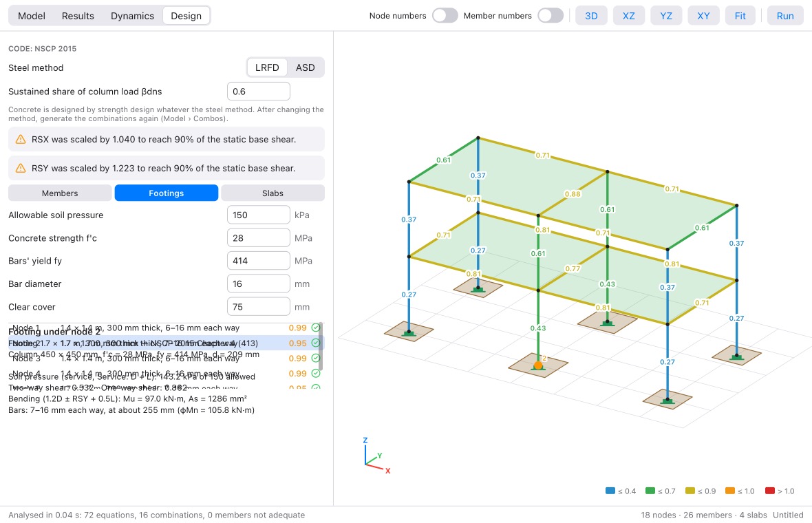
An isolated footing under every support: sized for the soil's allowable pressure, then designed for shear and bending.
Generated from NSCP 2015 Section 203 for LRFD or ASD, from the kinds of your load cases. Edit any factor.
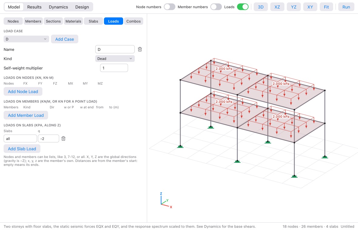
Fill in the tables, or start from a frame of so many bays and storeys. Loads go on nodes, members and slabs, and show on the structure as you enter them.
Pick a case or a combination and a diagram. Click a member for its forces along its length, or a slab for a map of its deflection and moments.
Periods, frequencies and the mass each mode carries. The spectrum and static seismic cases join the combinations with one click.
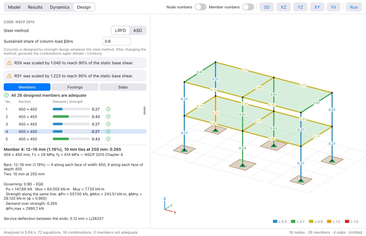
Every member coloured by demand over strength. Click one and read the calculation: the strengths, the governing combination, the bars.
Footings drawn in plan under their columns, each with its size, thickness, bars and the checks behind them.
The Examples menu opens ready-made structures. Some can be checked by hand.
An engineer should know where a tool stops. Girder says so in its guide, and here.
Girder is an aid to an engineer's judgment. Check its results against your own before building on them.
Girder runs on macOS, with Windows to follow.